Tools
Parts
-
-
During this process, you will be exposing high voltage wire connections. Make sure you POWER OFF the printer and UNPLUG it from the wall!
-
-
-
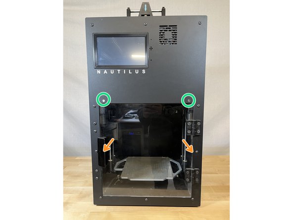
Remove the 10 M5 x10mm screws that secure the front panel
-
Hold the front panel as you remove the final screws to ensure that it doesn't fall forward.
-
-
-
Gently pull the front panel away from the printer. It will slide off the two metal rods circled in green.
-
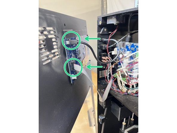
Be careful! There are two wires attached to the back of the front panel.
-
Carefully unplug the two wires that are connected to the display on the back of the front panel.
-
Set the front panel aside in a safe place.
-
-
-
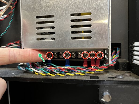
Make sure your printer is turned OFF and UNPLUGGED from the wall. These terminals carry dangerous voltage when the printer is plugged in and turned on.
-
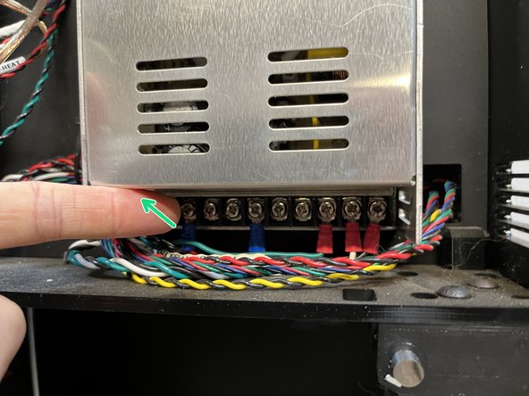
Lift the plastic cover that protects the wire terminals on the power supply.
-
Loosen the 5 screws holding down the wires 4-5 turns.
-
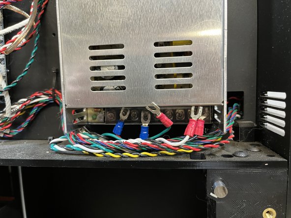
Carefully remove all 5 wires by sliding them down from the screw terminals. See the second image.
-
-
-
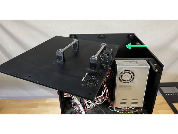
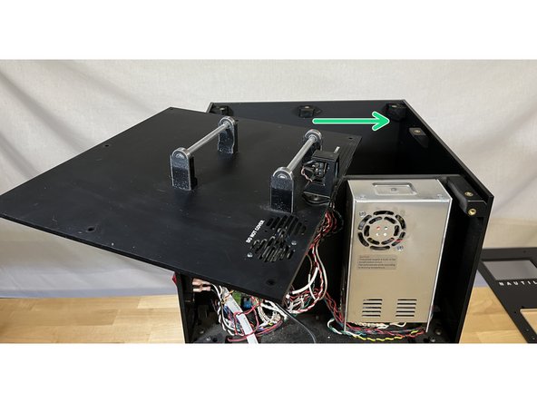
Remove the 7 screws securing the top panel.
-
Rotate the top panel to the left side as shown in the second image.
-
Careful when rotating the panel not to knock it off the top of the printer as there are still wires attached.
-
-
-
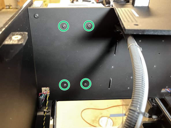
With the top panel shifted to the side you can access the 4 screws securing the power supply to the electronics panel.
-
Unscrew the 4 screws securing the power supply and remove it from the printer.
-
You can discard your old power supply via your local area's electronic waste disposal methods.
-
-
-
Remove any packaging materials from the new power supply and place it in the printer.
-
Make sure that no wires get stuck behind the power supply or get pinched.
-
Secure the new power supply to the electronics panel with the four screws located at the back of the electronics panel.
-
-
-
Slide the top panel back on.
-
Insert all screws that secure the top panel, but do not fully tighten.
-
Tighten the screws circled in Red first.
-
Tighten the screws circled in Blue last.
-
-
-
Lift the plastic cover that protects the wire terminals.
-
You may need to loosen the wire terminal screws before inserting the wires in the next steps.
-
-
-
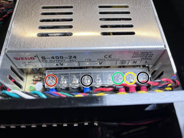
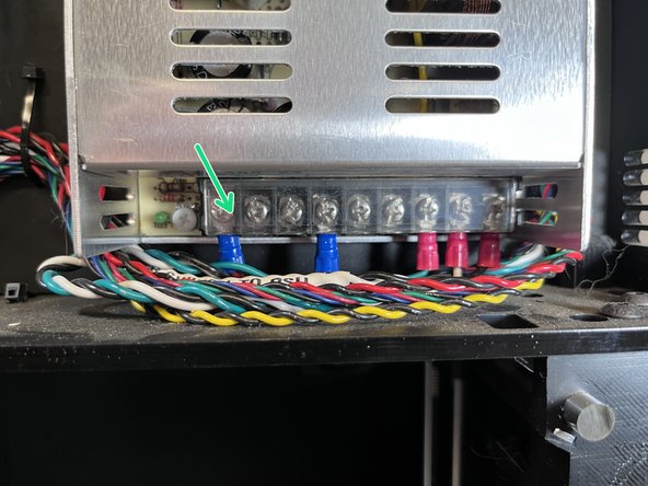
The first image is color-coded with the locations for each wire. In this image, yellow represents the white wire.
-
Start on the left with the Black and Red wire pair.
-
The Red wire goes in the left-most +V terminal. Insert the wire by sliding up under the square washer and tighten the screw.
-
The Red wire goes in the left-most -V terminal. Insert the wire by sliding up under the square washer and tighten the screw.
-
Now attach the Green, White, and Black wires on the right.
-
The Green wire goes in the Ground terminal. Insert the wire by sliding up under the square washer and tighten the screw.
-
The White (circled in yellow) wire goes in the N terminal. Insert the wire by sliding up under the square washer and tighten the screw.
-
The Black wire goes in the right-most terminal marked L. Insert the wire by sliding up under the square washer and tighten the screw.
-
-
-
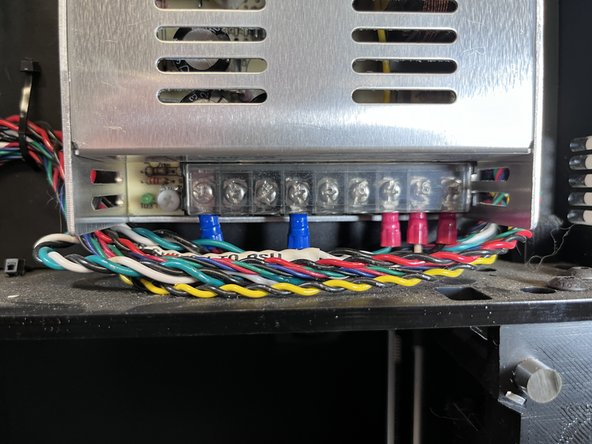
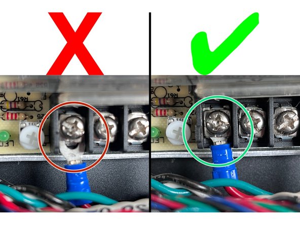
It is very important to double-check the connection of all your wires to the wire terminals. Make sure each wire is installed correctly and secure.
-
If you can see a gap between the spade connector at the end of the wire and the terminal, reinstall the spade connector.
-
There should be no gap between the spade connector and the terminal. A gentle tug on the wire should result in NO movement of the spade connector in the wire terminal.
-
-
-
Close the clear plastic cover over the power supply wire terminals.
-
-
-
Plug the two front panel wires into the appropriate connectors on the back of the display.
-
The micro USB cable goes on top and the ribbon cable goes on the bottom.
-
-
-
Place the front panel on the printer making sure not to pinch any wires in the electronics enclosure.
-
The protruding metal rods slide into holes on the front panel circled in green.
-
Check that the door magnets haven't fallen out. They are located in the square back brackets halfway up on the left and right sides of the door. If they did fall out, double check the magnet polarity against the door before reinstalling the front panel.
-
-
-
Insert but do not fully tighten all 10 of the M5 x10mm front panel screws.
-
Tighten the 4 screws circled in Red first.
-
Tighten the 6 screws circled in Blue last.
-
-
-
You can now plug the printer back in and turn it on to make sure everything is working.
-
If you have any issues, power off the printer and unplug it immediately! Then contact Hydra Research support here
-